From the Bench
by Ben Lanza
Lighting Your Passenger Cars Just Got Easier!
It has taken me a few years, but I have the solution to the lighting issue for passenger cars. I have no idea whether or not anyone has come up with this solution or whether it has ever been tried, but my results are pretty nice. This circuit works best with DCC and Rail-Lynx as they both have constant voltage on the tracks. I tested it with cab control, but the threshold voltage is around 6-8 volts before they turned on. It has taken me a long time to find the product that will get this job done and it really works nicely.


![]()


Click on an image to make it open larger.
1. I started with an older passenger car that had lights originally, but they were removed when they burned out and never replaced. I removed the screws holding the body and end piece (fig. 1 & 2).
2. Removed the trucks, two screws (figs. 3 & 4). Remember to mark them so they are oriented (insulated) on the proper side of car. One truck right side other truck left side. Lights will not work if the insulated wheels are on the same side, both trucks. You can see this in fig. 4.
3. Removed the brass plates with the old wires from the bolsters (fig 5 is the old wires, which were cut).
4. Figure 6, shows the new wires soldered to the old brass plates.


5. Figures 7 & 8 shows the hole for the wire and figs. 9 & 10 shows the brass plates back in place.
6. Figure 11 shows the new wires where they come thru the floor and how I ran the left (black) wire to the right of the car. These wires will be shortened as necessary to complete the connections.


7. Figure 12 shows the LED (for the rear tail light) and its resistor (I went to a 620 ohm resistor), the styrene mounting strip I made to insulate the strip from the brass body, and the LED circuit strip used for the overhead lighting for the car. Bridge rectifier is not shown in this image.
8. The next image shows the red LED and resistor soldered to the end of the strip for the tail light. Figure 14 shows the completed strip before I attached it to the styrene and before I added the small bridge rectifier, which is necessary so the LEDs light if the track power is reversed.
9. Hot glue was used to mount the styrene onto the car. The LED strip has its own mounting tape on it so it can easily be attached to a plastic car without the styrene strip (that is how it is attached to the styrene). I also added tape around the tail light leads to prevent either of them from shorting to the body.

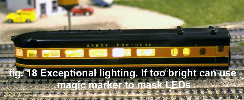
10. Figure 16 shows the testing of the LEDs You can see in figs. 18 & 20 the finished results. Remember, if the LEDs are too bright, you can use a magic marker to darken them.
11. There are no figs. 17 & 19.
12. You can also add a connector to the wires so they can be easily removed (I did not do this as my wires are pretty long.
13. Add the capacitor across the output of the rectifier if needed to eliminate flickering from dirty rails/wheels.
This particular project used 9 LEDs on the strip, but I could have used as little as 3 or 6 or for an 85 footer have gone to twelve (I am not counting the tail end LED.
This makes the job of adding LED lights to a passenger car that had old incandescent lights so easy, I just had to share it with you all. Questions? Drop me an email.
Component list for one regular passenger car:
1 LED strip (3, 6, 9 or 12 LEDs depending on length and brightness needed)
1 bridge rectifier Type NTE 5332
1 Red LED for rear tail light (if needed)
1 330 - 620 ohm resistor for rear tail light LED
1 1000ufd 35 volt electrolytic capacitor (if needed for flickering)
Wire
Tape (if needed)

Data
LEDs on strip are 3528 smd (strip has its own resistors)
120 degree light pattern
Strip is flexable with adhesive backing
.026 mA (strip of 6 LEDs)
3.7 Lumens per LED
Questions? Just email me at blqt@nls.net Thanks!